Channel slot drains
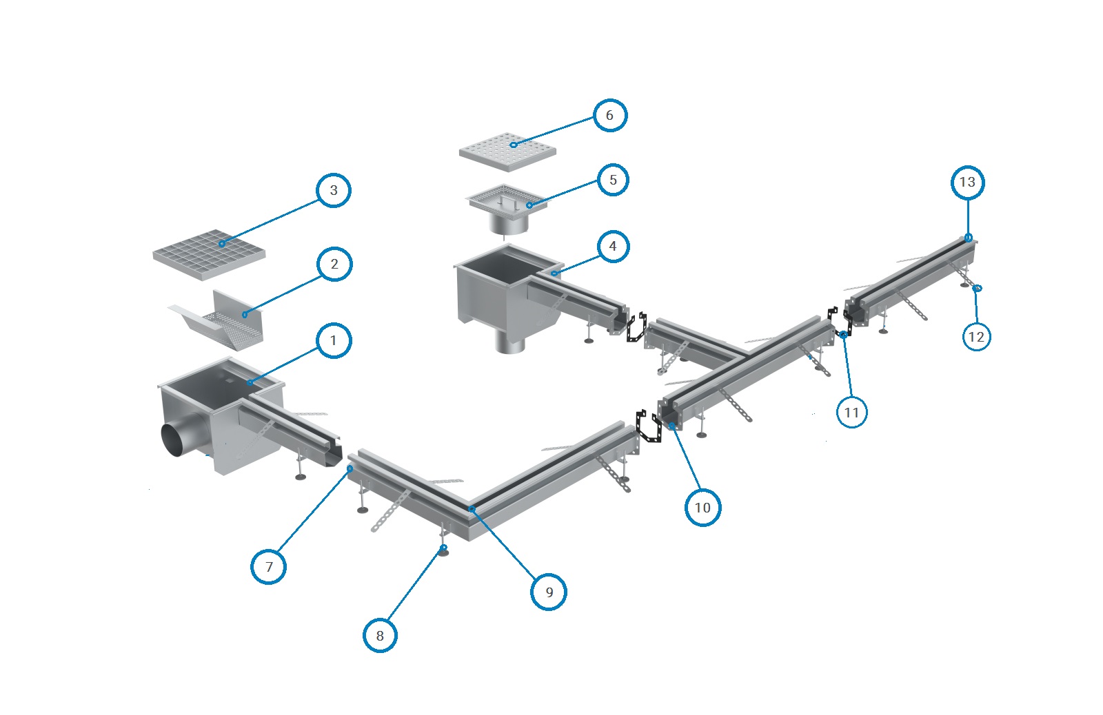 1. Horizontal outlet rectangular trap 2. Silt basket 3. Mesh grating 4. Vertical outlet rectangular trap 5. Foul air trap with silt basket 6. Perforated grating 7. Welded slot joint 8. Adjustable leveling feet 9. Angle slot joint 10. Flange slot joint 11. Silicon gasket 12. Anchor 13. Closing cap
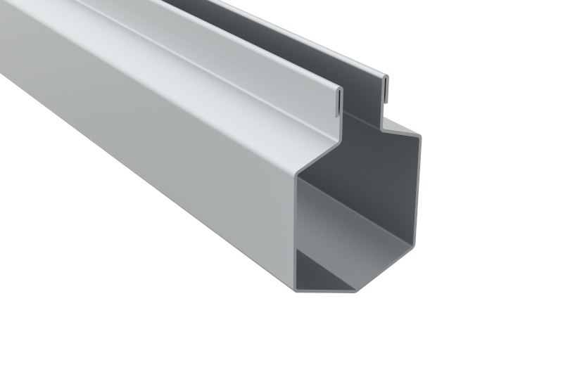
| CHANNEL SLOT DRAIN PROFILES | |||
| Picture | Scheme | Name | Product name |
 |
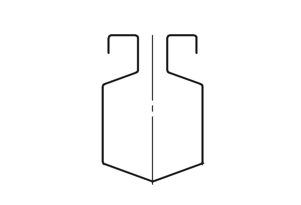 |
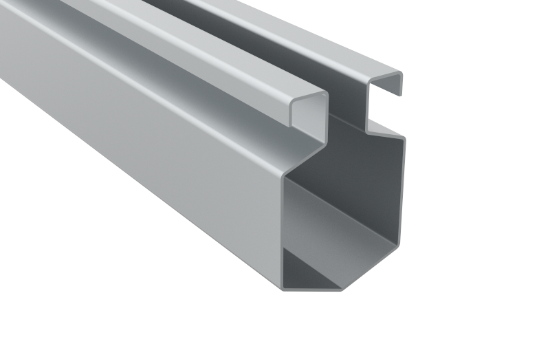
Standard cross section slots | LT.Slot |
 |
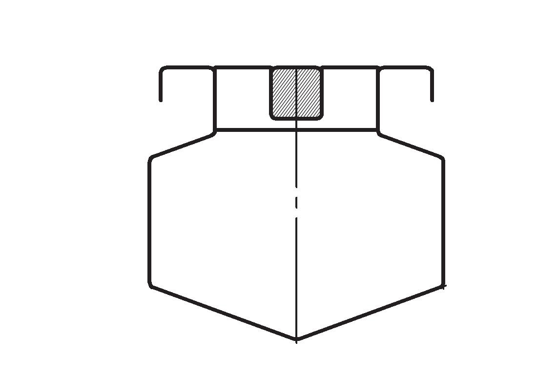 |
Duo slot drain | LT.Slot 2 |
 |
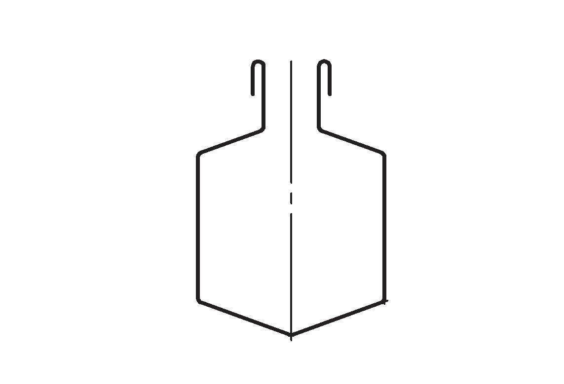 |
Slot with flattened flange | LT.Slot PL |
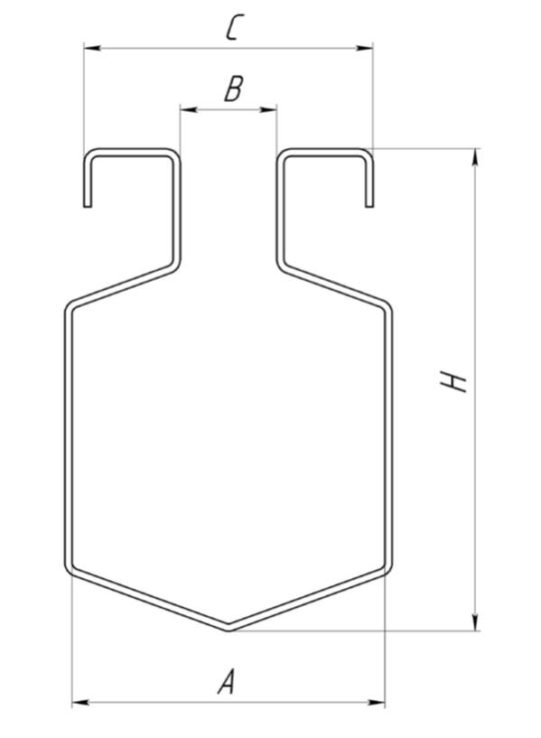
А - Working width
В - Slot for water drainage
С - Overall width
Н - Slot height
| CHANNEL SLOT DRAINS SIZE TABLE | |||||
| Product name | А, мм | В, мм | C, мм | Н min , мм | H max, мм |
| LT.Slot | 65 | 20 | 60 | 60 | 300 |
| LT.Slot2 | 105 | 20 | 100 | 70 | 300 |
| LT.Slot PL | 65 | 20 | 27 | 60 | 300 |
Advantages of stainless steel channel slot drains
These slot drains don’t require any gratings as water runs straight into the narrow slot. Thus, a slot drain is the simplest and the most efficient choice of drainage system. Slot drains might be produced with both variable and fixed width opening slots.
When installing slot drains it is necessary to take in account the slope:
- Floor slope for drainage of waste water flows (and fluids)
- The slot slope to the drainage point of the slot system (wastewater and fluids)
When installing variable width opening slots the slope of the floor to the slots should be provided. In order to overcome the difficulties in water drainage the slope should be no less than 0.5% which is equivalent to 5 mm per 1 meter.


